Hardware of Arduino System Part 1
Arduino在IoT系统中主要负责连接sensors和actuators,实现Perception Layer的信息输入与输出
Arduino Uno
Arduino development kit包含开发板、sensors、LED、motor等组件,可以组合成不同的IoT实验
Uno的特点:成本较低、容易使用、支持丰富
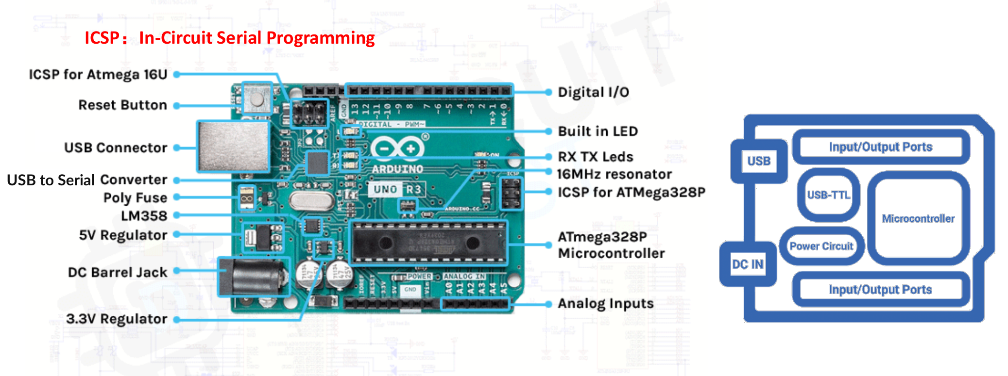
Core Microcontroller
ATmega328P是Uno中执行程序的核心microcontroller,属于8-bit AVR(最基本的数据处理宽度是 8 bit)
采用RISC(Reduced Instruction Set Computer)architecture,包含131条指令,其中多数可以在一个clock cycle内执行
具有32KB Flash memory,用于存储程序
通过ICSP(In-Circuit Serial Programming)将Arduino bootloader烧录到chip中
ATmega328P使用16MHz resonator提供clock, clock period与frequency的关系为T = 1/ f
T = 16 × 1 0 6 1 = 62.5 ns
这是一个clock cycle的时间,不代表每条指令都只需62.5ns
Secondary Microcontroller
Uno R3使用ATmega16U2作为USB-to-Serial converter,让电脑通过USB连接ATmega328P的UART serial port
Reset button连接到ATmega328P的PC6/RESET pin,正常情况下Reset引脚保持HIGH,通过10kΩ resistor上拉;按下时接到GND,使chip reset
Serial Communication
Parallel communication:用多条data lines同时传输多个bits
Serial communication:在一条data stream中逐个传输bits
接收端根据时钟的每一个周期就去读取Data线上是0还是1
按时间收到的bits不能直接当作从最高位到最低位书写的binary number
例:右侧波形依次收到1 1 0 0 1 0 1 0,对应D0到D7;重排为D7到D0后:
( 01010011 ) 2 = ( 83 ) 10 = ( 53 ) 16
左侧示意图是另一组数据:D7到D0为01001011,对应75 / 0x4B,不要与右侧波形混用
Binary / Hexadecimal / ASCII
一个hexadecimal digit对应4 bits,例如A = 1010、F = 1111
一个unsigned 8-bit number有2 8 = 256 2 8 − 1 = 255 0xFF
ASCII(American Standard Code for Information Interchange)用数值表示character,例如'A' = 65 = 0x41
Baud Rate / Bit Rate
Baud rate:每秒传输的symbols数量,单位为baud
Bit rate:每秒传输的bits数量,单位为bps(bits per second)
一个symbol可以表示多个bits;如果有M log 2 M
Hardware of Arduino System Part 2
Clock
Arduino Uno上有两个16MHz的clock元件,分别是16 MHz Quartz crystal oscillator(给 ATmega16U)和16 MHz Resonator(给核心微控制器 ATmega328P)
共同作用都是产生稳定、周期性的时钟信号,控制运行的周期
Power Path Control
Arduino Uno可以通过不同方式供电,如USB、DC barrel jack或Vin等
使用外部电源时,power path control会切换供电路径,隔离USB供电以保护USB port,避免外部电源反向进入USB
Voltage Regulator
Arduino 芯片能直接承受的最高输入电压大约5V
Voltage Regulator(稳压器)可以将外部电压转为合适的输入电压
Arduino LEDs
Uno有4个onboard LEDs:
Power LED:显示是否供电
RX LED:显示USB-to-Serial接收活动
TX LED:显示USB-to-Serial发送活动
Built-in LED:连接到digital pin 13,可用于Blink实验
Arduino Ports
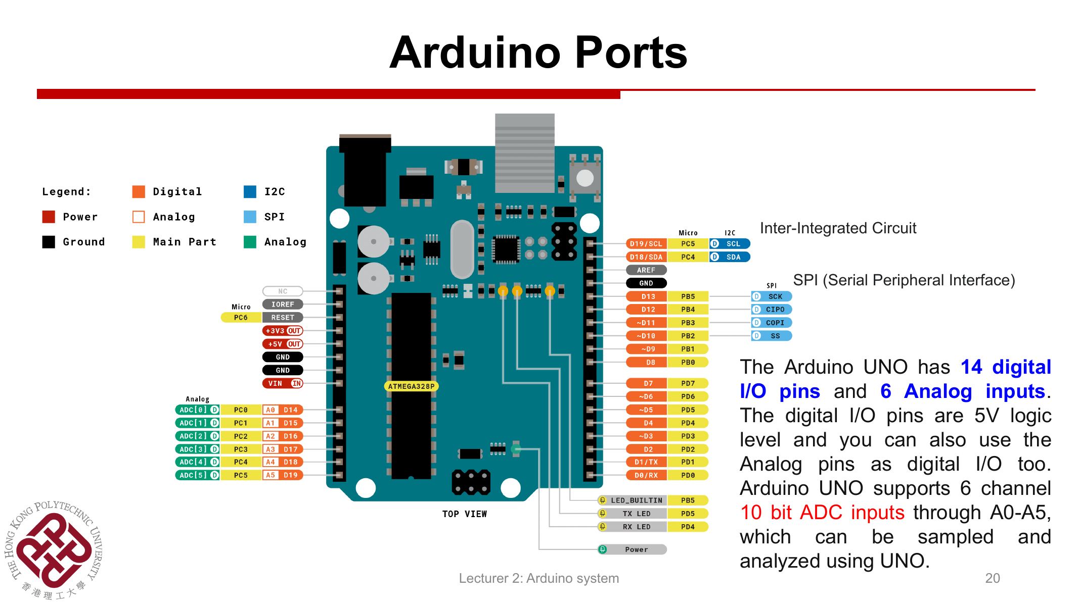
Arduion Uno有14个digital I/O pins:D0-D13,使用5V logic level,只能表示两种逻辑状态(HIGH/LOW)
还有6个analog input pins:A0-A5,连接10-bit ADC,可以表示2 10 = 1024
Arduino Programming Language(API)
Arduino程序称为sketch,通常在Arduino IDE中编写
基于c++
Structure: Sketch
setup():每次power-up或reset后执行一次,用于初始化variables、pin modes、serial communication等loop():在setup()之后反复执行,用于读取sensor、判断条件并控制输出程序的执行顺序为setup() → loop() → loop() → ...
void setup () { pinMode ( 13 , OUTPUT); Serial. begin ( 9600 ); }
void loop () { // 在这里重复执行读取、判断与输出 } Structure: Syntax
//:single-line comment;/* ... */:block / multi-line comment;用于结束一般statement,{ ... }用于包住function或control structure中的代码
Structure: Operators
arithmetic operators:+、-、*、/
comparison operators:==、!=、<、<=、>、>=
=是assignment,将右侧的值存入左侧variable;==是comparison,判断两个值是否相等Boolean operators:!(NOT)、&&(AND)、||(OR)
例:digitalRead(2) == HIGH && digitalRead(3) == HIGH要求两个输入都为HIGH
Functions: Digital I/O(Lecture #2, pp.46–47)
pinMode(pin, INPUT / OUTPUT):设置pin作为输入或输出;INPUT为high-impedance,适合读取外部信号,OUTPUT为low-impedance,可source / sink current。Uno的A0-A5也可以用于digital I/O,因此pinMode(A0, OUTPUT)是合法的
digitalWrite(pin, HIGH / LOW):将digital output设为逻辑高/低;在Uno上约为5V / 0V。digitalRead(pin)读取digital input,返回HIGH或LOW。输入pin不能悬空:未连接时读数可能随机变化。下例沿用课件D7按钮控制D13 LED;接线补充为外部下拉:D7经按钮接+5V,同时D7经约10 kΩ电阻接GND。按钮松开时电阻将D7拉低,按下时D7为HIGH;LED使用板载D13。
int ledPin = 13 ; int inPin = 7 ; int val = 0 ;
void setup () { pinMode (ledPin, OUTPUT); pinMode (inPin, INPUT); }
void loop () { val = digitalRead (inPin); digitalWrite (ledPin, val); } Functions: Analog I/O / PWM
analogRead()
analogRead(pin)通过ADC将输入电压转换为integerUno的ADC为10-bit,共2 10 = 1024
默认reference voltage为5V时,每一级约为:
Δ V = 1024 5 V ≈ 4.9 mV
例:analogRead(A0)读取A0上的sensor / potentiometer电压;返回的是ADC code,不是直接以V为单位的电压,最终print或计算时记得进行转换
analogWrite() / PWM
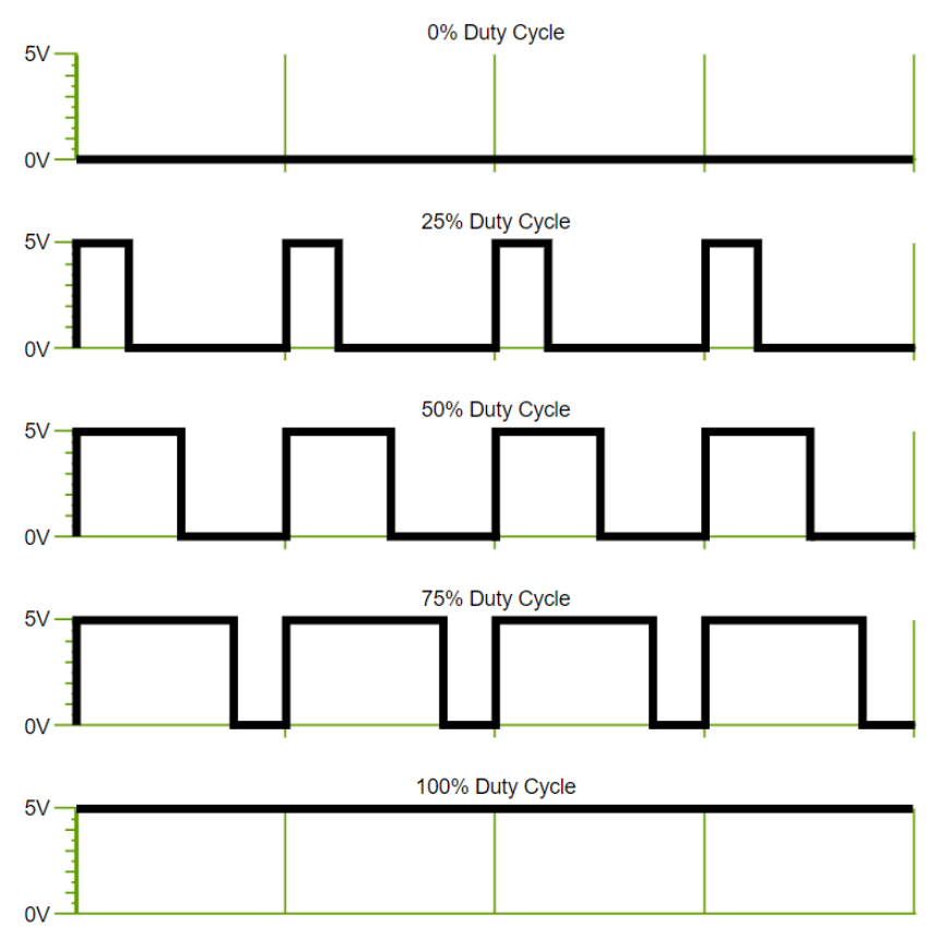
analogWrite(pin, value)在Uno支持PWM的pin上输出PWM wave,value范围为0-255PWM(Pulse Width Modulation)通过快速切换HIGH / LOW,并改变HIGH持续时间的比例来控制平均输出
duty cycle(占空比)为D = t HIGH / T
Uno的analogWrite()不是直接输出一个恒定的中间电压;例如约50% duty cycle仍然是0V / 5V交替的wave
Structure: Control
if:条件为true时执行对应代码if / else if / else:依次判断,执行第一个满足条件的branch,之后跳过其余branchesfor:适合已知次数或有counter的重复操作;顺序为initialization → condition → body → incrementwhile:只要condition为true就继续循环,需要确保条件最终可以变为falsereturn:结束当前function,也可以将一个value返回给调用方
if (temperature >= 70 ) { // Danger } else if (temperature >= 60 ) { // Warning:60 <= temperature < 70 } else { // Safe:temperature < 60 }
for ( int i = 0 ; i < 5 ; i ++ ) { // 重复5次,i依次为0、1、2、3、4 }
以下按课件p.37整理。完整sketch需分别上传运行,不能把多个setup() / loop()拼在一起。下面的while为放在function内的语法片段:条件成立时重复执行,更新计数值后条件最终变为false:
int var = 0 ; while (var < 200 ) { // 在这里执行一次重复操作 var ++ ; }
return会结束当前function并把值交回调用方。下例读取A0,读数大于400时返回1,否则返回0;补充setup() / loop()演示如何调用并打印返回值:
int checkSensor () { if ( analogRead (A0) > 400 ) { return 1 ; } else { return 0 ; } }
void setup () { pinMode (A0, INPUT); Serial. begin ( 9600 ); }
void loop () { int result = checkSensor (); Serial. println (result); delay ( 100 ); }
课件的LED亮度示例按PWM值从0渐亮至255,再渐暗至0;D9支持PWM。以下补齐pin初始化并整理为可单独运行的sketch(Lecture #2, p.37):
const int PWMpin = 9 ;
void setup () { pinMode (PWMpin, OUTPUT); }
void loop () { int direction = 1 ; for ( int i = 0 ; i > - 1 ; i += direction) { analogWrite (PWMpin, i); if (i == 255 ) { direction = - 1 ; } delay ( 10 ); } } Data: Constants
Boolean判断中,0为false,任意非零值为true,包括-1、2等
HIGH / LOW表示pin的logic level,与Boolean条件的概念不同对Uno的OUTPUT pin,HIGH约为5V,LOW约为0V
integer constants可以用不同bases书写,以下四种都表示123:
123 // decimal 0b 1111011 // binary,前缀0b 0 173 // octal,前缀0 0x 7B // hexadecimal,前缀0x Data: Data Types
int
在Arduino Uno / ATmega平台上,int是16-bit(2 bytes),范围为− 2 15 = − 32768 2 15 − 1 = 32767
signed integer用two’s complement(补码)表示负数;对正数的bit pattern取反后加1可以得到对应负数
float
float用于保存带小数的近似值,在Uno上占32 bits(4 bytes),范围约为± 3.4028235 × 1 0 38 两个integers做division会先进行integer division,丢弃小数部分,更多情形如下所示:
int x = 1 ; int y = x / 2 ; // 0 float z = ( float )x / 2.0 ; // 0.5 float a = x / 2 ; // 0.0,右侧先做integer division float b = ( float )x / 2 ; // 0.5,先将一个operand转为float char
char保存一个character,单引号表示character,如'A';双引号表示string,如"ABC"character以编码数值保存,如'A'与ASCII value 65对应
array
array是同一类型的一组elements,通过index访问,index从0开始
int myInts[ 6 ]; // 声明6个elements,未显式初始化 int myPins[] = { 2 , 4 , 8 , 3 , 6 }; // 自动得到size为5 int mySensVals[ 5 ] = { 2 , 4 , - 8 , 3 , 2 }; char message[ 6 ] = "hello" ; // 5个characters + '\0'
局部automatic array若未显式初始化,其元素初值不可假定;全局或static array默认初始化为0。字符数组结尾需要额外一个位置保存null character \0,所以"hello"需要6个elements
Functions: map()
将一个range中的value线性映射到另一个range:
map (value, fromLow, fromHigh, toLow, toHigh); int outputValue = map (sensorValue, 0 , 1023 , 0 , 255 );
此处将10-bit ADC的0-1023映射为PWM所需的0-255,使输入范围与输出范围匹配
课件也使用val / 4完成近似转换,因为1023 / 4在integer division下得到255
补充说明:map()使用integer arithmetic,会截去小数部分;它不会自动限制超出输入范围的数值
Functions: Time
delay(ms):暂停一般程序执行指定的milliseconds,delay(1000)为1秒millis():返回当前程序开始运行以来经过的milliseconds返回类型为32-bit unsigned long,约49.7天后会overflow回到0(课件约写为50天)
课件p.50的串口计时示例每次打印启动以来的毫秒数,并等待1秒以降低输出频率;它仍使用delay(1000),所以不是non-blocking计时:
unsigned long myTime;
void setup () { Serial. begin ( 9600 ); }
void loop () { Serial. print ( "Time: " ); myTime = millis (); Serial. println (myTime); delay ( 1000 ); } Functions: Communication
Serial.begin(9600):初始化serial communicationSerial.print():输出human-readable ASCII text,不自动换行Serial.println():输出后增加carriage return \r和newline \ninteger默认以decimal输出,可以用第二个argument指定base;float的第二个argument指定保留几位小数
Serial. print ( 78 ); // "78" Serial. print ( 78 , BIN); // "1001110" Serial. print ( 78 , HEX); // "4E" Serial. print ( 1.23456 ); // "1.23",默认2位小数 Serial. print ( 1.23456 , 4 ); // "1.2346" Serial. println ( 'A' ); // 显示A并换行 Serial. println ( 65 ); // 显示65并换行
Serial.print(78)发送文本"78",即两个ASCII characters,不是直接发送一个数值为78的raw byte
IoT Examples(Written By Codex)
Example #1: Blink the LED
Digital output:pin 13输出HIGH / LOW,使LED交替亮灭
每次亮1秒、灭1秒,因此一个完整Blink cycle为2秒
void setup () { pinMode ( 13 , OUTPUT); }
void loop () { digitalWrite ( 13 , HIGH); delay ( 1000 ); digitalWrite ( 13 , LOW); delay ( 1000 ); } Example #2: Dim the LED
Analog input + PWM output + serial output
Potentiometer(电位器)的中间端连接A0,两侧连接5V和GND;LED通过限流电阻连接D9
数据流:A0电压 → analogRead() → map() → analogWrite(9, ...) → LED brightness
int sensorValue = 0 ; int outputValue = 0 ;
void setup () { pinMode (A0, INPUT); pinMode ( 9 , OUTPUT); Serial. begin ( 9600 ); }
void loop () { sensorValue = analogRead (A0); outputValue = map (sensorValue, 0 , 1023 , 0 , 255 ); analogWrite ( 9 , outputValue);
Serial. print ( "sensor = " ); Serial. print (sensorValue); Serial. print ( " \t output = " ); Serial. println (outputValue); delay ( 2 ); }
sensor value接近0时LED很暗,接近1023时LED很亮;改变的是PWM duty cycle
Example #3: Soil Moisture Sensor
Analog input + digital output + serial output
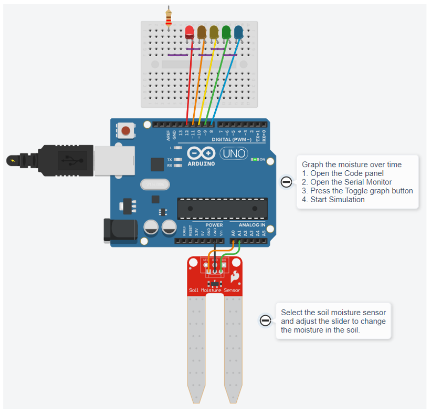
课件称为humidity sensor,图中实际使用soil moisture sensor(土壤湿度传感器)
A0作为OUTPUT给sensor短时供电,A1作为INPUT读取moisture value
读取前A0设为HIGH并等待10ms,读取后设为LOW,以减少sensor长期通电导致的metal corrosion
这个moisture value是0-1023的ADC读数,不是湿度百分比
根据读数只点亮一个LED:
< 200:D12200-399:D11400-599:D10600-799:D9>= 800:D8
以下将课件中的nested if整理成等价的else if,并用for关闭全部LED:
int moisture = 0 ;
void setup () { pinMode (A0, OUTPUT); pinMode (A1, INPUT); Serial. begin ( 9600 ); for ( int pin = 8 ; pin <= 12 ; pin ++ ) { pinMode (pin, OUTPUT); } }
void loop () { digitalWrite (A0, HIGH); delay ( 10 ); moisture = analogRead (A1); digitalWrite (A0, LOW); Serial. println (moisture);
for ( int pin = 8 ; pin <= 12 ; pin ++ ) { digitalWrite (pin, LOW); }
if (moisture < 200 ) { digitalWrite ( 12 , HIGH); } else if (moisture < 400 ) { digitalWrite ( 11 , HIGH); } else if (moisture < 600 ) { digitalWrite ( 10 , HIGH); } else if (moisture < 800 ) { digitalWrite ( 9 , HIGH); } else { digitalWrite ( 8 , HIGH); } delay ( 100 ); }
先将全部LED设为LOW,再点亮对应LED,避免前一次的LED一直保持亮起
A0在这个例子中是供电输出,A1才是analog读取输入,不能只根据A前缀判断它的用途
Example #4: Sensor Threshold and LED(Lecture #2, p.57,课件任务整理)
按课件任务读取连接A1的humidity sensor analog output,将读数输出到Serial Monitor;读数小于200时点亮D2上的LED。接线:sensor的VCC/GND接开发板5V/GND、analog output接A1;LED串联限流电阻接D2与GND。
以下为依据课件任务整理的独立sketch;需单独上传运行,不能与其他示例拼接。
const int sensorPin = A1; const int ledPin = 2 ; int sensorValue = 0 ;
void setup () { pinMode (sensorPin, INPUT); pinMode (ledPin, OUTPUT); Serial. begin ( 9600 ); }
void loop () { sensorValue = analogRead (sensorPin); Serial. println (sensorValue);
if (sensorValue < 200 ) { digitalWrite (ledPin, HIGH); } else { digitalWrite (ledPin, LOW); } delay ( 100 ); } 链接